
Safety Plc Schematic Diagram For Overland Uzbekistan

Relay Circuits and Ladder Diagrams
Unlike schematic diagrams where the association between relay coils and relay contacts is represented by dashed lines, ladder diagrams associate coils and contacts by label. Sometimes you will find relay contacts labeled identically to the coil ( coil labeled CR5 and all contacts for that relay also labeled CR5) while other times you will find suffix numbers used to distinguish individual ...

overland belt conveyor control schematics
safety plc schematic diagram for overland conveyor « mill gold ; Belt Conveyor Efficiencies: Power, Strength and Life. Belt conveyor engineering has taken new form to meet the users demands for more . Figure 1 is a schematic used ... Get Price. circuit diagram of belt conveyor plc control ; circuit diagram of conveyor belt youtube. jan 15, 2014 circuit diagram of conveyor belt, links ...
Safety Interlock Switches
Use two safety interlock devices and a safety module for a high level of integrity. Flexible actuator Courtesy of Steven Engineering, Inc. 230 Ryan Way, South San Francisco, CA, Main Office: (650) 58 89200 Outside Local Area: (800) 25 89200 . 188 Banner Engineering Corp. • Minneapolis, • • Tel: Selection ...

Programmable Logic Controllers (PLC) | Ladder Logic ...
They exist as commands in a computer program—a piece of software only—that just happens to resemble a real relay schematic diagram. Equally important to understand is that the personal computer used to display and edit the PLC's program is not necessary for the PLC's continued operation. Once a program has been loaded to the PLC from the personal computer, the .
Programmable Logic Controllers, Basic Level (Textbook)
KarnaughVeitch diagram B30 . TP301 • Festo Didactic BVI Chapter 4 Design and mode of operation of a PLC B33 Structure of a PLC B33 Central control unit of a PLC B35 Function mode of a PLC B37 Appliion program memory B39 Input module B41 Output module B43 Programming device/Personal computer B45 Chapter 5 .


DISTRIBUTED CONTROL SYSTEM (DCS) And PROGRAMMABLE .
13 Annexure II Existing DCSPLC hookup diagram 116 – 116 14 Annexure III Tentative bill of material for DCS 117 – 119 15 Annexure IVTentative bill of material for PLC 120 – 121 16 Annexure V List of components to be removed for DCS 122 – 123 17 Annexure VI List of components to be removed for PLC 124 – 125 18 Annexure VII I/O count for DCS and PLC 126 – 126 19 Annexure ...

Module 5 Logic Diagrams
learning to read logic diagrams. Figure 1 presents a schematic for a large pump, and Figure 2 shows the same pump circuit using only logic gates. It is obvious that when the basic logic symbols are understood, figuring out how the pump operates and how it will respond to various combinations of inputs using the logic diagram is fast and easy, as compared to laboriously tracing through the ...
Introduction to Programmable Logic Controllers (PLC's)
Modifying A PLC Program Relay ladder diagram for modified process. The change requires that the manual pushbutton control should be permitted to operate at any pressure but not unless the specified temperature setting has been reached. Lecture – Introduction to PLC's MME 486 – Fall 2006 40 of 47 Modifying A PLC Program Relay ladder diagram for modified process. If a relay system were used ...

Guardmaster Configurable Safety ...
The safety function that is performed by the guard locking interlock meets the safety performance requirements of SIL CL2 per IEC 61061:2012 and SIL 2 per IEC 61508:2005 and has a Category 3 structure that can be used in systems requiring Performance Levels up to PLd per ISO 138491: 2006. The circuit executes a Stop Category 1.

AC500S Safety PLC
AC500S Safety PLC range extreme conditions XC modules. Applicable for harsh environmental appliions like harbor cranes, mobile platforms, wind (offshore and onshore), etc. Physical dimensions, basic electrical characteristics and software compatibility correspond with the standard AC500S version. Costsavings in engineering and operation.
TB6600 Stepper Motor Driver
Safety Statement The author of this document is not liable or responsible for any accidents, injuries, equipment damage, property damage, loss of money or loss of time resulting from improper use of electrical or mechanical or software products. Assembling electrical CNC machine components like power supplies, motors, drivers or other electrical components .

Programmable Logic Controllers, Basic Level (Textbook)
KarnaughVeitch diagram B30 . TP301 • Festo Didactic BVI Chapter 4 Design and mode of operation of a PLC B33 Structure of a PLC B33 Central control unit of a PLC B35 Function mode of a PLC B37 Appliion program memory B39 Input module B41 Output module B43 Programming device/Personal computer B45 Chapter 5 Programming of a PLC B47 .

Typical Wiring Diagrams for Push Button Control ...
diagram. l The schematic or line diagram includes all the components of the control circuit and indies their function. * The control station wiring diagram is a representation of the physical station, showing the relative positions of units, the suggested internal wiring, and connections with the starter. Symbols common to most circuits are explained on Page 5. Less common symbols are ...


The SISTEMA Cookbook 1
3 From the schematic circuit diagram to the safetyrelated block diagram Structure Category to EN ISO 138491 and Typical representation in the 10 particular features safetyrelated block diagram Twochannel, with fault detection . Category 4 (as for Category 3, but also robust against the accumulation of two undetected faults) Note: Each channel may comprise one or more component(s ...
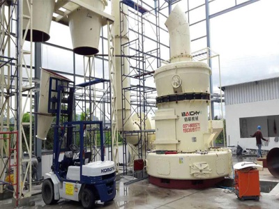
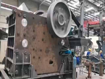
safety plc schematic diagram for overland conveyor
/safety plc schematic diagram for overland conveyor. PLCControlled of a Conveyor System I. Programmable Logic Controller are conducted to progress with the works on the upgraded flexible manufacturing system, where the controller system is programmable. The main challenge faced for the project of PLCcontrolled of a conveyor system is to . Get Price. PLC Conveyor Motor Ladder Logic .
Latest Posts
- smb minig recrutement de septembre
- كسارة خام ومصنع لتجهيز
- حجم الحجر المدخلات كسارة الحجر
- قطع غيار مطحنة في مصر
- مسبقا في سحق المعدات الشعبي
- طاحونة بيليه يموت للبيع
- آلة معدنية سحق في المملكة العربية السعودية
- آلة كسارة مستعملة للبيع في بولندا
- كسارة مخروطية هيدروليكية متينة
- السيليكا معالجة الرمال منشأة
- موردي محطم الكلي في جواهاتي
- تهتز مخاطر التغذية
- شاحنات محجر الحجر الجيري روجرز سيتي
- مصنع تكسير حجر الجرافيت
- مخطط عملية منجم خام الحديد
- Cema Belt Thailand Design Torrent
- Kaolin Fine Indonesia For Sale
- Dawu Compound Pendulum Jaw Chile
- Zenith Malaysia Zenith Vsi Malaysia
- Coal Washing Process Flow Diagram
- Stone Dominica Machine Control
- Zirconium Ball Mill
- Portugal Impact Portugal Price
- Msi Gold Shaker Table For Sale
- Grain Grinding Mill Uses
- Almieda Bolivia Spares In Bolivia
- Small Malaysia Machine In Malaysia
- Mobile Cone Crushers For Hire In Angola
- Granite Quarry Operators In Malaysia
- Fluorescent Lamp Crushers
